

Poor power factor occurs when inductive or capacitive equipment, such as motors, refrigeration units, or HVAC systems, causes the current and voltage to become out of phase. Inductive equipment draws current that has both real (useful) and reactive components. The reactive component doesn’t produce useful work but is required to sustain magnetic fields in inductive devices, increasing the total current flow for the same real power output.
Power Factor Correction (PFC) reduces the reactive component of current by supplying the required reactive power locally, typically through capacitor banks or active electronic units. This lowers the total current drawn from the grid, improving electrical efficiency, reducing heat losses, and cutting demand charges for customers on demand-based tariffs. Maintaining a power factor close to unity (between 0.9 lagging and 1.0) is both good practice and a compliance requirement under NSW network standards.
What is Power Factor?
Power factor describes how efficiently electrical power is being used in an electrical system. It is the ratio of real power (measured in kilowatts, KW), which performs useful work, to apparent power (measured in kilovolt-amperes, KVA), which represents the total power supplied by the network.
The difference between the two is known as reactive power (KVAr). Reactive power does not perform useful work, but it supports the magnetic and electric fields needed for equipment such as motors and transformers to operate.
A lower power factor means that more current must flow to deliver the same amount of useful power. This extra current increases energy losses and can reduce the available capacity of the electrical infrastructure. For large commercial and industrial customers billed on a kVA-based tariff, this can translate directly into higher demand charges.
In practice, achieving a perfect power factor of 1.0 is impossible because every electrical system contains some inductance and capacitance. However, under the NSW Service and Installation Rules, customers are required to maintain a power factor between 0.9 lagging and unity to ensure efficient and compliant operation.
What Causes Poor Power Factor?
Poor power factor typically occurs when certain types of electrical equipment cause the current and voltage to fall out of phase. The most common cause is inductive loading, where devices rely on magnetic fields to operate. Motors, compressors, HVAC systems, welding machines, and older lighting systems with ballasts all draw both real power (to perform work) and reactive power (to sustain magnetic fields).
When inductive loads are running, the current waveform lags behind the voltage waveform, as shown in Figure 1, because energy is continually stored and released within magnetic fields. This phase difference reduces the proportion of real power available for useful work. The greater the phase lag, the lower the power factor.
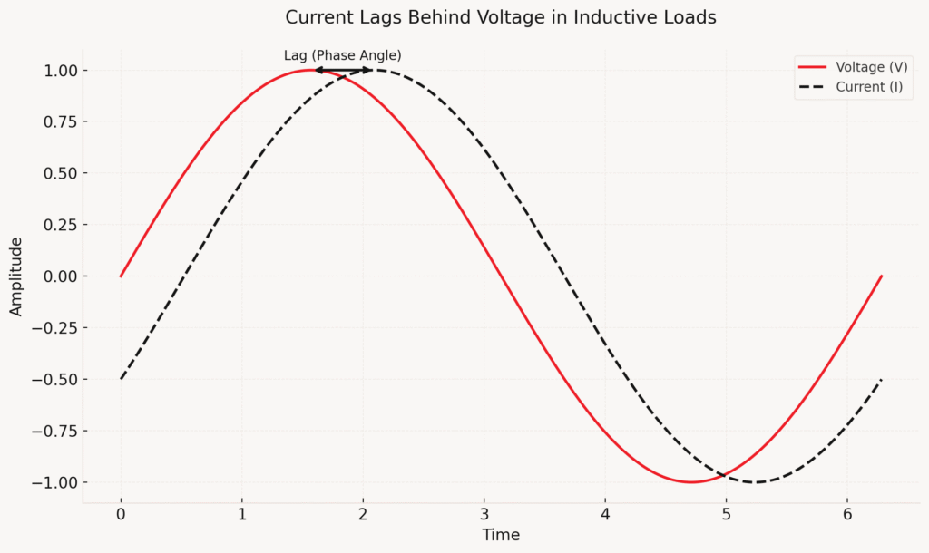
Figure 1: Power Lag Diagram
While inductive equipment is the main contributor, capacitive or non-linear electrical loads can also distort the power factor. Equipment such as variable speed drives (VSDs), LED lighting, and computers can introduce harmonics that affect the true power factor of the system.
Power factor can also fluctuate with changing site conditions. For example, HVAC and refrigeration systems operating for longer periods in summer increase reactive power demand, while machinery that cycles on and off can cause the site’s overall power factor to vary throughout the day. If these fluctuations are not corrected, they can reduce network efficiency, limit electrical capacity, and result in higher kVA demand charges for large industrial electrical sites.
How does power factor correction work?
Power Factor Correction (PFC) improves the efficiency of an industrial electrical system by supplying reactive power locally, rather than drawing it from the electricity network. By balancing the reactive power required by inductive loads, PFC reduces total current and helps maintain a power factor close to unity (see Figure 2).
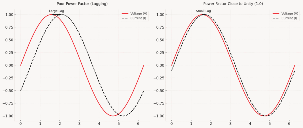
Figure 2: Power Factor Close to Unity Diagram
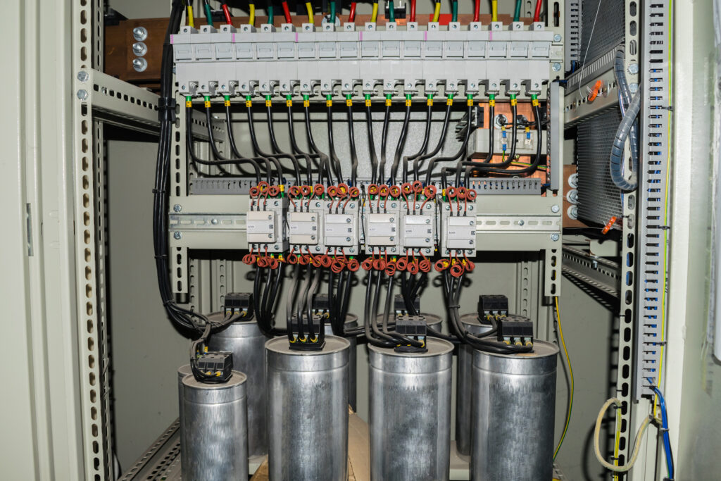
The most common approach is to install capacitor banks, which supply leading reactive current that offsets the lagging reactive demand from inductive equipment. Fixed capacitor banks suit sites with steady, predictable loads, while automatic or active PFC systems respond dynamically to changing demand.
Active PFC units use electronic controllers to continuously monitor voltage and current, injecting the exact amount of reactive power required in real time. Many modern systems also include harmonic mitigation features. Harmonics, high-frequency distortions (see Figure 3) caused by non-linear equipment such as Variable Speed Drives (VSDs), computers, LED lighting, and welders, can cause overheating, voltage distortion, and equipment stress. Managing both harmonics and power factor is therefore essential for system stability and reliability.
In practice, effective power factor correction involves selecting the right combination of capacitors, automatic control units, and harmonic filters to match the site’s load characteristics.
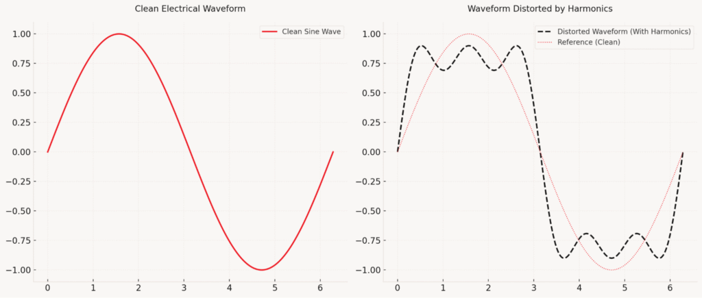
Figure 3: Harmonic Distortion
Do I need approval for Power Factor Correction?
In New South Wales, installing or upgrading Power Factor Correction (PFC) equipment requires approval from your local electricity distributor. Under the Service and Installation Rules of NSW (Section 6.2), an application must be submitted for each PFC connection, except where fitted to individual items of equipment with low power requirements.
The approval process ensures that new PFC equipment does not create a leading power factor, interfere with ripple-control signals, or introduce harmonics that could affect network stability.
Types of Power Factor Correction Equipment
The right Power Factor Correction (PFC) equipment depends on the site’s electrical load profile, the degree of load variation, and whether harmonics are present in the system. The main types used in industrial electrical applications are outlined below.
Fixed Capacitor Banks
Fixed capacitor banks provide a constant level of reactive power and are best suited to smaller installations with steady, predictable loads. They are commonly used to correct the power factor of individual motors or small groups of continuously operating machines. Because they supply a fixed output, they are less effective where demand varies significantly.
Automatic Capacitor Banks
Automatic banks are made up of multiple capacitor stages that connect or disconnect as the load changes. This stepped control allows the system to maintain a consistent power factor across fluctuating demand periods, such as in manufacturing plants with variable production schedules or warehouses with intermittent HVAC operation.
Detuned Banks and Harmonic Filters
In systems with harmonic distortion, standard capacitor banks can interact with those harmonics, creating resonance and potentially stressing both the PFC unit and the wider electrical network. Detuned banks and harmonic filters prevent this by using reactors or tuned circuits to shift the system’s resonant frequency or block unwanted harmonic currents. These are essential in facilities with many Variable Speed Drives (VSDs), welders, or sensitive electronics. Under the NSW Service and Installation Rules (Clauses 6.4–6.8), harmonic filtering or ripple blocking may be required to prevent interference with the network’s load-control signals.
Active PFC Units
Active Power Factor Correction systems use advanced electronic controllers to monitor voltage and current continuously, injecting precisely the right amount of reactive power in real time. They respond instantly to rapid load changes and can simultaneously reduce harmonic distortion. Although more expensive to install, active PFC delivers the most stable results in environments with unpredictable or highly dynamic loads, such as welding workshops or food-processing facilities. Over time, their improved efficiency and network stability often provide the best long-term return on investment.

Selecting the right PFC equipment requires careful assessment of the site’s load characteristics and compliance with local distributor requirements. A qualified power quality specialist can determine whether fixed, automatic, or active correction — or a combination of these — will deliver the best technical and financial outcome.
Benefits of Power Factor Correction
Installing Power Factor Correction (PFC) delivers measurable financial, operational, and environmental benefits for industrial and commercial facilities. Beyond improving efficiency, it can significantly reduce electricity costs and enhance overall system performance.
Lower Electricity Bills and Tariff Savings
Many Australian businesses are charged based on their maximum kVA demand, not just their energy consumption (kWh). A poor power factor inflates this figure, sometimes increasing electricity costs by 20–25%. By improving power factor, PFC lowers apparent demand and helps avoid penalty charges.
Improved Energy Efficiency
With PFC operating correctly, more of the supplied electrical power is converted into useful work rather than reactive current. This improves energy utilisation across the site, reducing distribution losses and improving overall system efficiency.
Increased Capacity Without Upgrades
By reducing the reactive component of current flow, PFC lightens the load on transformers, switchboards, and cabling. This frees up existing electrical capacity, allowing expansion or new equipment installation without the need for major infrastructure upgrades, often deferring costly capital expenditure.
Stable Voltage and Power Quality
Balanced reactive power helps stabilise voltage levels, minimising fluctuations that can lead to overheating, tripping, or premature equipment wear. When combined with harmonic filters, PFC systems also mitigate waveform distortion, ensuring reliable operation of sensitive electronic and control equipment.
Longer Equipment Life
Running closer to unity power factor means electrical equipment operates under less stress. Motors, transformers, and conductors experience less heat generation, extending service life and reducing maintenance costs over time.
Supports Sustainability and ESG Goals
Improved power factor reduces overall network losses and indirectly lowers a facility’s carbon footprint. For organisations reporting under ESG or sustainability frameworks, demonstrating improved electrical efficiency supports both environmental responsibility and long-term operational resilience.
VSDs and power factor correction
Variable Speed Drives (VSDs) improve motor efficiency by adjusting speed to match load demand and often operate with a high displacement power factor. However, they can generate harmonics that distort the current waveform. These harmonics reduce the overall power factor, even if the displacement power factor is good. Therefore, while VSDs enhance energy efficiency, they often require harmonic filters or dedicated PFC systems to maintain power quality across the site.

How is Power Factor Correction Equipment Installed?
Power factor correction equipment is usually installed within a site’s main switchboard or distribution board, where it can directly interact with the electrical supply and offset the reactive power drawn by connected loads. By integrating the correction system at this central point, the benefits flow through to the entire facility, improving efficiency across all equipment.
The process typically begins with an industrial electrical engineer or power quality specialist, who analyses the site’s load profile to determine the correct system size and configuration. Proper sizing is essential: under-correction limits effectiveness, while over-correction can cause a leading power factor or network resonance. These conditions are prohibited under the NSW Service and Installation Rules (Section 6.1.1) and can lead to instability or interference with ripple-control signals..
Once the system design is finalised, the equipment is installed at the switchboard, connected to the appropriate protection and metering points, and integrated with harmonic filtering if required. Under NSW regulations, a connection application and network approval must be obtained before energising the unit. Following installation, the electrical contractor issues a Certificate of Compliance for Electrical Work (CCEW) and, if applicable, a Notification of Service Work (NOSW).
Commissioning and Monitoring
Commissioning involves verifying that the PFC equipment switches correctly, responds to load changes, and maintains the power factor within the target range. Measurements are taken under various load conditions to confirm stability and safety. Modern systems often include digital controllers with on-board displays or remote monitoring capability, allowing ongoing performance tracking and early fault detection.
Maintenance of Power Factor Correction Equipment
Once installed and commissioned, Power Factor Correction (PFC) equipment requires regular maintenance to ensure long-term reliability and compliance. Routine servicing helps detect early signs of component degradation and maintains the system’s efficiency over time.
The most common wear items are capacitors, which naturally lose capacity due to heat and electrical stress; contactors, which degrade through repeated switching; and cooling fans, which can accumulate dust or suffer bearing failure.
Routine inspections should be carried out at least once a year, with more frequent checks for sites operating under high inductive loads, extended production shifts, or elevated ambient temperatures. During these inspections, technicians verify that:
- Capacitors retain correct capacitance and show no bulging or leakage.
- Contactor and protection devices operate correctly.
- Ventilation systems and fans are clean and functional.
- Controllers respond accurately to load changes and maintain the target power factor.
Modern PFC units often include built-in diagnostics and remote monitoring capabilities that provide real-time alerts for component failure or temperature rise. Complementary tools such as thermal imaging, harmonic analysis, and insulation resistance testing are also useful for predictive maintenance.
Contact Sydney Engineering for Power Factor Correction Support
Managing power factor effectively is one of the most practical ways for businesses to improve energy performance and reduce operating costs. Sydney Engineering specialises in the assessment, design, and implementation of electrical solutions that meet both operational needs and compliance requirements.
Whether you are upgrading existing infrastructure or integrating new equipment, we can provide a PFC solution that optimises performance, stability, and long-term savings.
Contact Sydney Engineering today to arrange a consultation with our engineering team and discover how a professionally designed power factor correction system can lower costs, improve system reliability, and maximise capacity in your electrical network.
